This article describes how to use Frontline Spatial Editor to add Pins and other content to a workflow.
Adding pins
- Click on Add > Pin in the top menu.
- Move the mouse over the model and click at the desired location over the model to add the pin. The other options/buttons of the editor are disabled until you place the pin.
- An added pin can be moved and rotated along three different axes. They are shown in three different colors: blue, green, and red. Just like markers, pins can be repositioned using the transformation gizmos or by using the Transform menu on the right.
4. Click on Objects > Snap to unsnap the pin and reposition it.
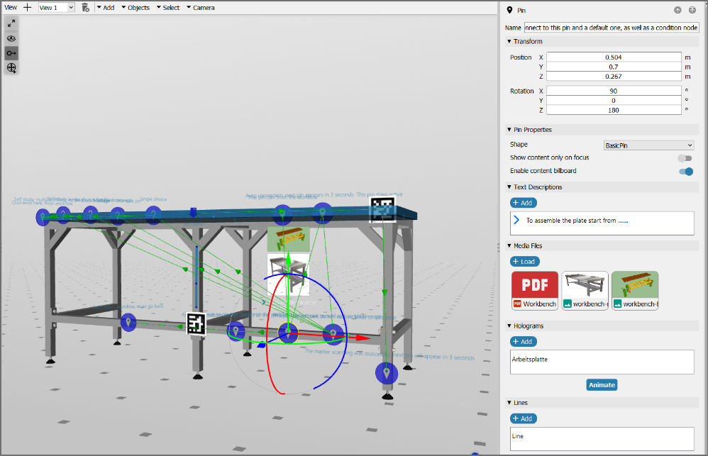
The menu on the right offers the following options:
- Defining the pin's name and type
- Changing the content behaviour
- Choosing icons to be shown over a pin with text notes
- Adding images, videos, PDFs, and audio for reference
- Adding holograms and animations
- Adding lines
Pin name and types
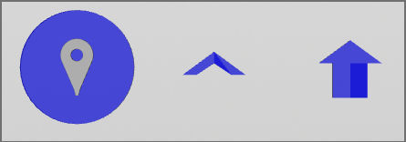
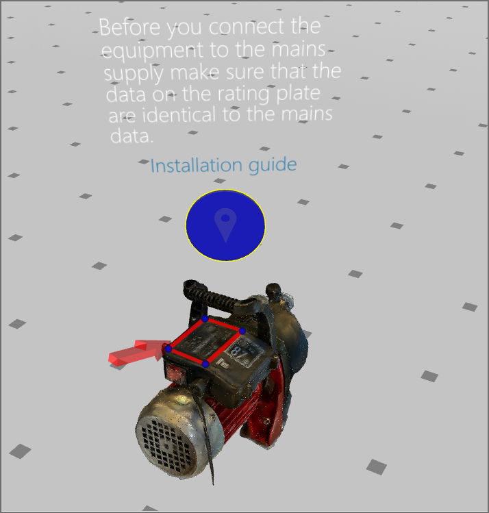
A pin's name is shown over the pin, whereas the pin's type defines its appearance (as shown in the below image from left to right):
- Basic pin
- Small pointer
- Large pointer
Pin transformation
You can change the position and rotation of a selected pin using either the desired axis in the 3D viewer or the position and rotation options on the menu on the right.
Pin Properties
This section allows you to configure the properties of a pin.
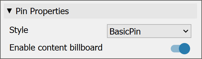
- Style: Allows you to configure the pin's shape to be displayed.
- Enable content billboard: This allows you to toggle the display of pin content. When enabled, the pin contents are always rotated around the vertical axis to face the user in the Viewer.
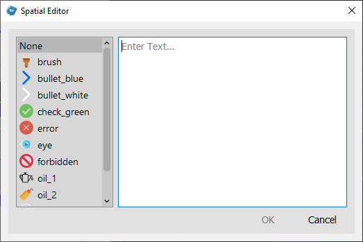
Icons and notes
Pressing on + Add under "Text Descriptions" opens the item box. Select an icon from the list on the left and add a note in the textbox. For example, add an eye icon for visual inspection.
Rich text: A pin's name and notes can be formatted by using rich text notation. Just write your text between the following tags. The rich text formatting will then be visible later in Spatial Workplace.
For more information, please see the documentation on rich text tags.
Images, videos, PDFs, and audio
Multimedia content can be added with the + Add button under "Media Files". For example, the picture of the timing belt pin shows the correct placement of the belt.
Supported formats:
- Images: PNG, JPG, JPEG, and TIF/TIFF
- Videos: MP4, AVI, MOV, MPEG, GIF, FLV, OGG and WMV
- Audio: WAV
Note: PDFs are only supported by the iOS and Android versions of Spatial Workplace.
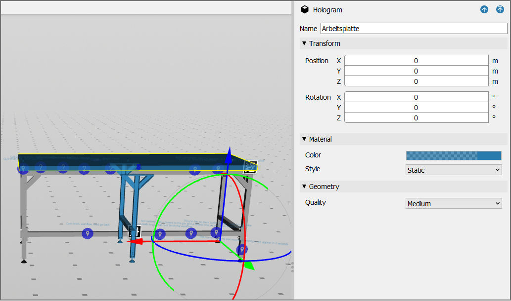
Holograms
In the editor, it is also possible to associate a part or different parts of a model with a pin. When this pin is visualized, the part(s) will be highlighted over the real-life component. Select a pin and click on + Add under the Hologram section of the right menu. The hologram selection mode opens. Now, the user can select an individual part or an assembly of parts to be associated with the pin and then press Enter.
Note: Alternatively, you can select assemblies via the Scene Explorer. Multiple parts can be selected by holding Ctrl and clicking on them one after another. For more information, please see the page on scene explorer.
By default, the parts remain highlighted in light blue. The color, quality, and style of the hologram can be changed by clicking on the hologram to edit and using the settings on the right. The same highlight will appear over the real-life component when the pin is visualized in Spatial Workplace.
Default hologram color: The light blue default hologram color can be changed via the settings.
Scene states: Holograms are meant to highlight a part of the model. If you want parts of the model or the whole model to be visible with their vertex colors, you can use scene states. For more information, please see the scene state nodes section
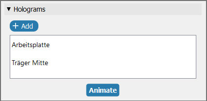
Hologram animations
All holograms added to pins can be animated to move and rotate when the pin is reached. After adding one or more holograms, click on Animate. The animation timeline will open with a list of holograms on the left. Select a hologram from the list and click on Add Key Frame. Now, put the position of the blue animation handle further down the timeline. Move or rotate the hologram with the gizmo and again click on Add Key Frame. Move the handle between the keyframes to see the animation behaviour.
The user can:
- Press the Play button to preview the animation.
- Change the distance between the keyframes to change the speed of the animation.
- Add as many keyframes as desired for different holograms.
- Change the frame duration of the timeline through the frame/frame input fields.
- Toggle the repeat arrows to make the animation loop infinite and play again once it reaches the end.
- Press Confirm to save the animation or Discard to delete the changes.
Lines
Another way of highlighting parts of the model is by drawing lines over them.
- Select the pin and click on + Add under the Lines section of the right menu.
- Define the lines by clicking on different points on the surface of the model.
- Lines will be drawn between the defined points.
- Click on Done to end the line drawing.
- If desired, change the line's color and name via the Edit button in the menu on the right.
Note: The default line color can be changed via the settings.
Adding quiz pins
To test certain skills of a worker on a machine, for example, the user can place quiz pins to the model that contain single-answer or multiple-choice questions. Click on Add > Quiz Pin at the top and place it over the desired part of the model. Just like any other pin, quiz pins can be repositioned using the transformation gizmos or by using the transform menu on the right. The order in which your pins are displayed is changed using the 2D connector. For more information, please see the page on connecting pins.
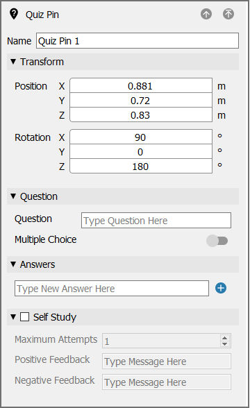
Using the right panel options of the quiz pin, the user can:
- Define the quiz pin's name (only relevant inside the editor).
- Transform the position and rotation of the quiz pin.
- Define a question.
- Define whether it is a single-answer or multiple-choice question.
- Add the answer(s).
- Define if this question is offered for self-study.
- If it is offered for self-study, define how many attempts the user has to answer the question.
- Decide on the feedback the user receives when answering the question.
Quiz pin name and question
The quiz pin name serves to identify it inside Spatial Editor. However, this name will not appear in Spatial Workplace. Spatial Workplace will only display the question.
Single-answer and multiple-choice questions
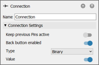
This setting defines how many correct answers need to be selected before the question is considered to be answered correctly. If a single is selected, the user needs to choose only one correct answer, even if the question has more than one correct answer. If multiple is selected, the user needs to select all the correct answers for the response to be considered correct. Once the correct answer or answers have been selected, the user receives positive feedback - if defined for this question - and the True connection of the quiz pin is activated, which leads to the corresponding next pin being displayed. Connections that come out of a quiz pin are already of the Binary and True type by default.
Maximum attempts
This defines how many times a user can select a wrong answer before the question is considered to be answered incorrectly. Once all available attempts have been used up, the user receives negative feedback - if defined for this question - and the False connection of the quiz pin is activated, which leads to the corresponding next pin being displayed. Connections that come out of a quiz pin are already of the Binary and True type by default, but this can be changed in the connection inspector after selecting the connection.
Answers
Any number of possible answers can be added to a question by clicking on the Add Item button under Answers. Tick the checkbox next to all the correct answers for the question.
Feedback
It is possible to give immediate feedback to the user about whether the question was answered correctly or incorrectly. Tick the checkboxes for positive/negative feedback and enter the respective feedback message to be shown. Positive feedback will be displayed when the correct answer(s) have been selected. Negative feedback will be displayed when the user answers incorrectly. The maximum number of attempts for answering a question incorrectly before the negative feedback appears depends on the respective setting for a question.
Note: Without feedback, the user will not know if they answered the question correctly or not.
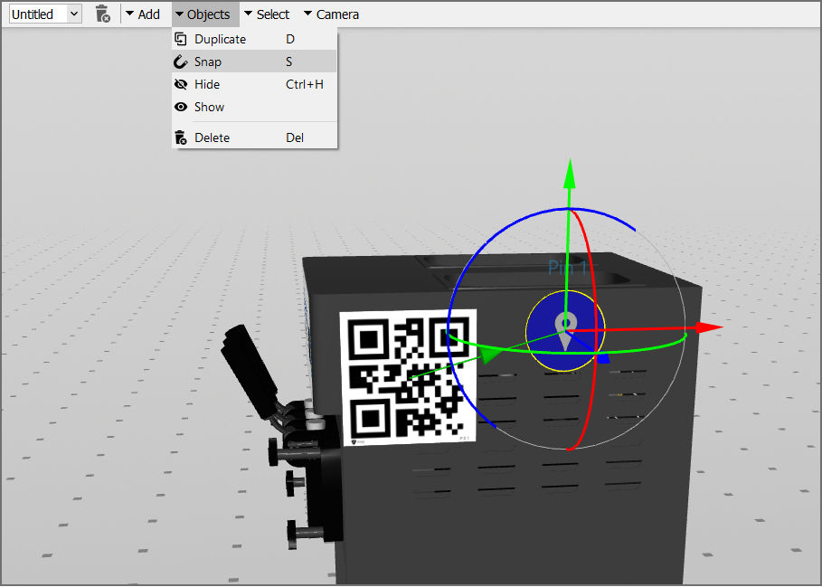
Additional actions via the Objects menu
Using the Objects option in the top menu, the user can:
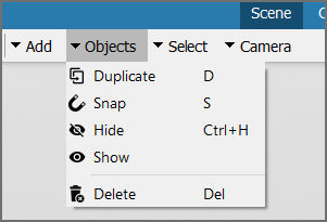
- Snap: Reposition the pin to another position over the surface of the model.
- Duplicate: Duplicate the pin at the same position and with the same content.
- Line: Draw lines over the model.
- Delete: Remove the pin and its contents from the model.
Note: To delete an item, the user can also select it in Scene Explorer and press Delete.
Scene Explorer
Open the Scene Explorer on the left side of the 3D scene to see a list of all pins, condition nodes, scene states, and spatial references used in the workflow. These are all nodes added to the scene.
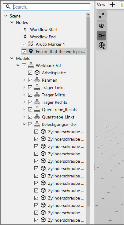
The user can add as many pins as desired to the model and enrich each of them with information. To edit any item, select it in the 3D scene or under Scene > Nodes and change its information via the settings panel that opens on the right.
Order of the Pins: The user can change the order in which the pins are visualized in Spatial Workplace by changing their connections in the Connector.
Adding new views to the workflow
In the same workflow, it is possible to set up distinct views for showing different predefined groups of items. For example, there could be one view for cleaning and another one for maintenance within the same workflow. The different views can be seen separately in Spatial Editor for easy organization.
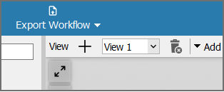
Each view only shows its own visible pins to avoid a cluttered 3D scene in the project. To add a new view, click on the + button next to View at the top left. A new view is created with the same items. It is possible to hide the items that are not relevant to a specific view and they will not be displayed there. Change the name of the view by clicking over its name in the dropdown menu.
Note: In the Spatial Workplace app, views are not relevant. All items in the workflow will be present. The different visibility settings defined for the various views are exclusively meant for organizational purposes inside Spatial Editor.
Recommended video links for this guide
Frontline Spatial | Adding pins and connecting them
Frontline Spatial | Transformation of Gizmos