Connections represent the course of a workflow and can be visualized both in the 3D view and in the 2D connector. In the connector, the user can see:
- The order in which the pins are to be shown
- Which pins appear together
- The different paths of the workflow
Pins are automatically connected linearly based on the order they are created in. This default route can be edited by managing the connections inside the 2D connector.
Connections in the 3D view
The connections are directly visible in the 3D view, as overlays on top of the model.
Viewing and editing
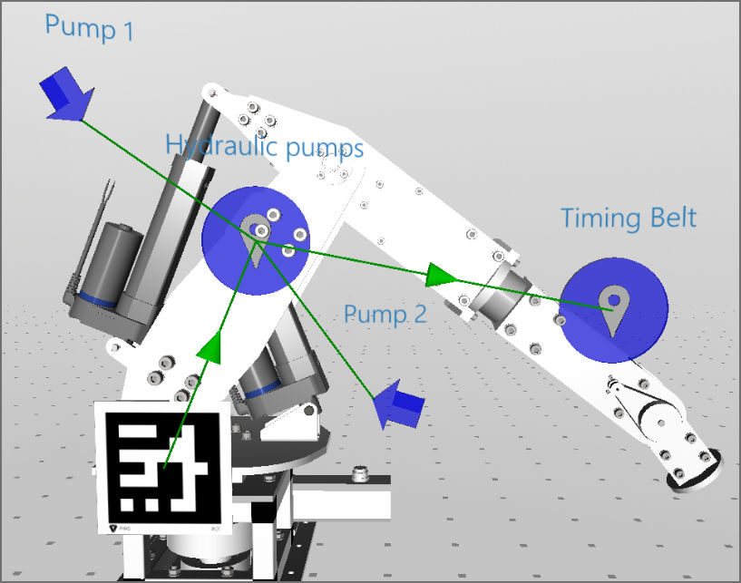
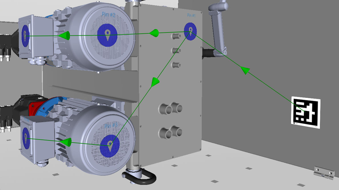
Green arrows represent the order in which the pins are shown in Spatial Workplace. Green lines connect two pins that are shown simultaneously in the same step. In the example in the below picture, the "Hydraulic pumps" pin is shown together with the two "Pump 1" and "Pump 2" pins after scanning the QR code and before the "Timing Belt" pin is shown.
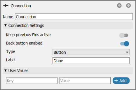
When selecting a connection, its behaviour can be changed via the menu on the right. The available options are:
- Type and Label: Define the kind of command that will activate this connection in the Spatial Workplace app.
- Keep previous Pins active: Forms the line connection between the pins. When this connection is activated, the previous pin will not disappear as it does by default.
- Back button enabled: Allows the user to return to the previous pin or step. This behaviour is set by default.
- Key-Value Pairs: Adds an attribute value to this connection. This function is not used in the out-of-the-box Spatial Editor application, but as a customization of behaviour in private projects.
Connection types
There are three types of connections: button, auto, and binary.
The Button type is the default and comes with the label "Done". When users reach a pin with this connection type, they will see a Done button that can be clicked to activate this connection and go to the next pin(s). If necessary, the user can change the label to a custom one.
The Autotype is for connections that are activated without the need for any user input. For such connections, you can define a delay in milliseconds. For example, if the delay is 5000, the connection will be triggered 5 seconds after it is reached.
The Binary type is used for the quiz pins and condition nodes. For more information, please see sections on either condition nodes.
Note: Auto connections with delay a of 0 are triggered immediately. This can cause unexpected behaviour where pins are seemingly skipped within a workflow.
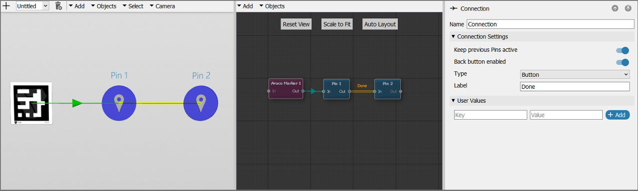
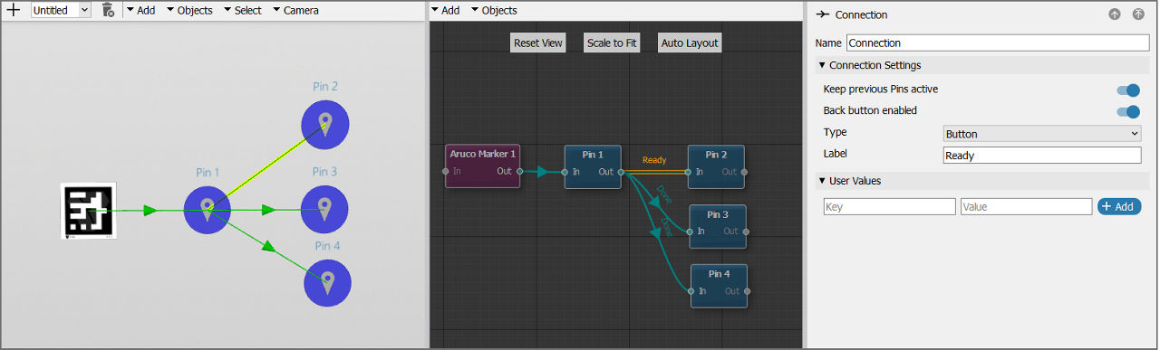
Auto connections with a delay of 0 can be also used to show more than one pin at the same time. To do so, activate the Keep the previous pin active option. In the below example, pin 1 and pin 2 will be shown at the same time after scanning the marker, because the type of the connection between them is set to Auto with a delay of 0 and with the previous pins kept active.
Another way to show multiple pins at the same time is having connections with the same label going to different pins. In the below example, the user sees pin 1 with two buttons: Done (which is the default label) and Ready (which is a custom label) after scanning the marker. If they click on Done, both pin 3 and pin 4 appear. If they click on Ready, only pin 2 appears instead.
Hiding connections
To hide green connections in the 3D scene, deactivate the Show Connections option in the toolbar at the top-left of the scene.
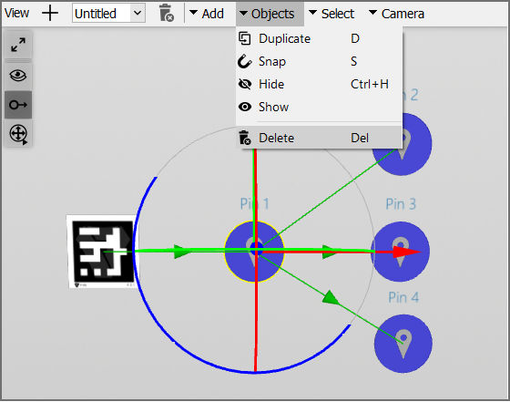
To delete a connection, select it and press DEL or go to Objects > Delete in the top menu.
The user cannot manually create new connections inside the 3D view. In the next section, we explain how to use the 2D connector to create connections.
Connections in the 2D connector
Viewing and editing
Activate the 2D connector by selecting Connector in the top menu of the editor. In this mode, the connections are shown in a more structured manner. The behaviour of the individual connections is exactly the same as in the 3D view. Arrows connect pins that are shown after each other, and lines keep previous pins active.

Select a connection to open its menu. On the top of the connector, there are three buttons to adjust the current view:
- Reset View: Resets the position and zoom factor of the window to the default values.
- Scale to Fit: Makes all markers and pins visible at the same time.
- Auto Layout: Allows you to automatically arrange markers and pins.
Creating new connections
To connect two nodes, click and drag from the Out connection dot of a pin or marker to the In connection dot of another.
Extra markers: When adding more than one marker, the extra ones will not be connected automatically. The user has to connect them manually. This allows the user to choose if the workflow can be started using different markers or if markers are placed in the middle of a workflow for calibration.
Using connections to create decision trees
The connections between pins work with a decision tree logic. This means that more than one arrow connection can be drawn from one pin to different other pins. The user can choose which path to follow when running the workflow in the Spatial Workplace app.
With default connection labels
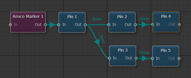
Connections with the same name are combined in Spatial Workplace. In the following example, the user will see only one Done button when visualizing pin 1 since the two connections coming out of it have the default connection label. After the user clicks on Done at pin 1, both pin 2 and pin 3 will appear.
Each of the two pins has a separate Done button, since their outgoing connections are two different nodes. Now, the user chooses the path to follow in the workflow, by selecting the corresponding button.
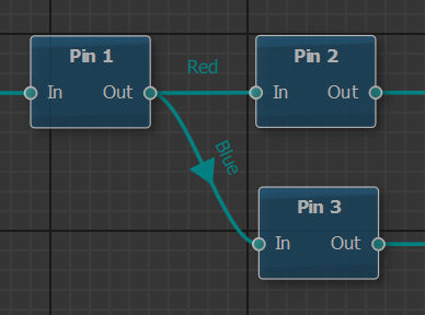
With custom connection labels
In this case, the connections coming out of pin 1 have different custom labels. In this case, the user sees two buttons in the Spatial Workplace app: Red and Blue. This means they already select the path to follow based on the button they choose.