Pins are used for adding content to a workflow. They are points of interest in space that are placed anywhere in the scene and are enriched with the content.
Adding the first pin
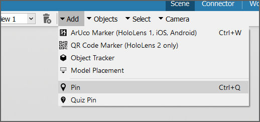
- Click on Add > Pin on the top menu of the Editor.
2. Move the mouse over the model and click at the desired location to add the pin. The other options/buttons of the Editor are disabled until you place the pin.
3. An added pin can be rotated and moved along the three axes; x, y, z. They are depicted in red, green, and blue, respectively. To move the pin so that it hovers over the model, use the arrows and transformation menu on the right.
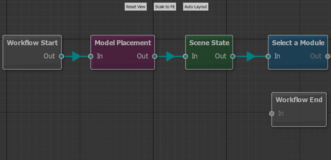
⇒The pin will automatically be added to the Connector as a node. The new pin is already connected to the Scene State node if the Scene State node was selected when the pin was added. The connections between the three nodes define the order in which the Workplace app will process and display the information.
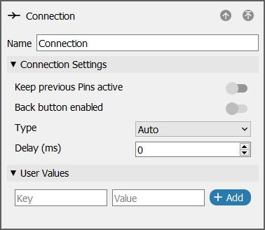
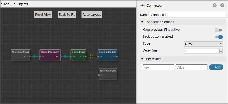
4. To see the options regarding connections, select one of these existing connections in the Connector. The menu on the right opens and shows that the connection is of type Auto with zero delays. This means that the connection immediately takes the user to the next node once it is reached. Except for defining the order in which the nodes are activated. Connections also provide the user with the ability to decide how and when the next node should be activated.
This is the desired default behavior for connections between the nodes used until now, so that all of them would happen at the moment when the workflow starts.
If the workflow is exported to Spatial Workplace now, these would happen:
- The Workflow starts at the Spatial Reference node that prompts the user to find the plane surface to position the model on the plane surface.
- It is connected to the Scene State Node that makes the whole model visible. Their connection is of type Auto with zero delays, so it appears directly.
- The Scene State node is also joined by an Auto connection with zero delays to the first pin.
It is helpful to give more informative or descriptive names to the pins. In this example, a good first instruction to give the users would be for them to select a module to get more information about it.
Select Pin 1 and on the menu to the right, change its name to Select a module.
The next step that the user would need to do is to create different buttons and pins for each of the modules to be included in the workflow.
Adding other pins
- Click on Add and choose Pin at the top bar and place this pin somewhere on the water pump.
- Use the colored arrows to move the pin in the 3D Scene, until the pin is floating next to the pump model. In the case of the image below, the green arrow would be used to bring the pin upward, and then the red arrow to bring the pin a bit to the right.
- Rotate the pin by dragging the green cycle. This is not a mandatory thing to do, but it displays how to use the transformation gizmos.
- It is also possible to do the repositioning by using the Transform Menu on the right.
- After repositioning the pin, rename it to Installation guide.
- To highlight the instructions on the water pump, create a rectangle of lines around them. To do that, click on the new pin. Then click on Add under Lines that is on the menu on the right.
- In the screen that appears, create the shape by clicking to create a point and clicking again to create another, and so on. With this, the rectangle will be created. To finish editing press, Enter.
Add a safety instruction pin
- To add a pin and to place it on the water pump, click on Add and choose Pin.
- You can move it by using the colored arrows, which are named Gizmo.
- Click on the pin, it will show the properties of the pin on the right side. Rename the pin to Safety Instruction.
- Add a connection between Select a module to Safety Instruction.
- Click on the connection in the Connector, and it will show the connection properties on the right.
- Add a label to the Safety Instructions Pin.
- You can highlight a part of the model by adding a hologram to the pin. To add a hologram to the pin, click on the pin, then click on Add under Holograms in pin's menu.
Add a component description pin
- To add another pin and to place it on the water pump, click on Add and choose Pin at the top of the bar .
- Move it by using the colored arrows named Gizmo.
- Click on the pin, it will show the properties of the pin on the right side. Change the name of the pin to component description.
- Add a connection between Select a module and Component Description and add a label to the Component Description connection.
Add an open water valve pin
- To add a pin and to place it on the water pump, click on Add and choose Pin at the top of the bar.
- You can move the pin by using the colored arrows named Gizmos.
- Click on the pin, it will show the properties of the pin on the right side. Rename the pin to Open Water Valve.
- Add a connection between Select a module to Oper Water Valve, Click on the connection in the Connector, and it will show the connection properties on the right.
- Add the Operation label.
This is how the workflow looks like after connecting the nodes:
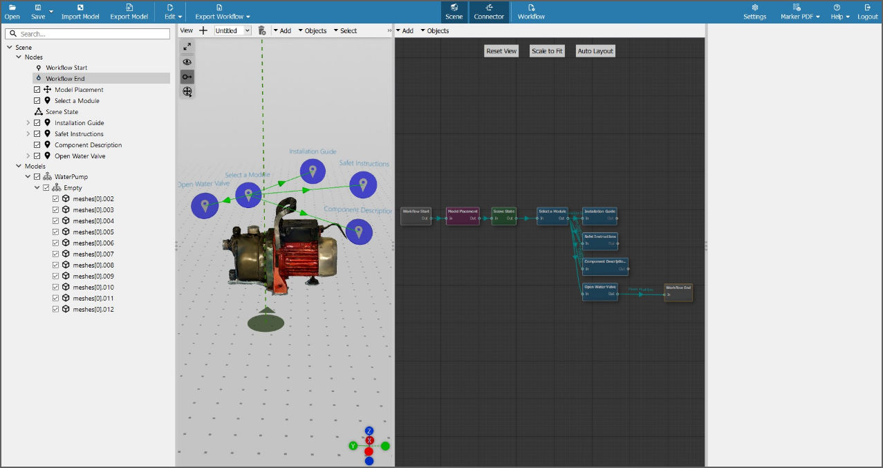
In the workflow above, the nodes - Installation Guide, Safety Instructions and Component Description are not connected with the Workflow End and only Open Water Valve is. This means that while running it, the user has to go back to Select a Module and go to the end of the workflow through the Open Water Valve.