After loading a model, you can add information to the workflow. To define where the model will be later displayed in the Spatial Workplace app, a spatial reference must be added to the workflow.
There are three types of references:
- Markers
- Object trackers
- Model placement
Note: Mixing different spatial reference types in a workflow is currently not supported.
Markers
A marker is used to position information that is to be displayed within a workflow at the desired spot over the real-life component. For this, at least one virtual marker needs to be added in the editor where the real-life marker will be in relation to the real-life component. Different devices use different types of markers. The virtual model is then loaded in Spatial Workplace according to the scanned position of the marker.
The following types of markers exist:
- ArUco marker: This type of marker is meant to be used with mobile devices (iOS and Android). The size of the marker can be adjusted by the user and can be between 1 and 99 cm. As a rule of thumb, markers with a size of 10 cm (12 cm with borders) or 15 cm (18 cm with borders) should be used, but the user has the option to select the size that works best with the respective component.
- QR code marker: This type of marker is meant to be used with a HoloLens 2. Again, the size can be adjusted by the user. The proposed default is 15 cm (17 cm with borders).
Note: For correct tracking, it is necessary to print the marker in the same size as it has been added in Spatial Editor.
To add a marker to your model:
- Click on Add on the top.
- Choose either ArUco or QR code marker depending on your requirements.
- Click on the surface of the model where you want to place it. The other options/buttons of the editor are disabled until you place the marker.
- To change the position of the marker on the model's surface, select it and click on Object > Snap in the top menu or press
Son the keyboard. - Change the position and rotation of markers independent of the model's surface by using the transformation gizmos or the Transform menu on the right.
6. On the right side, you can edit the marker's reference (ID and size).
Note: The virtual marker used in the editor must be the same as the real-life marker that is put on the real-life component when using Spatial Workplace, so ensure that the marker ID matches. It is important to print the correct marker and place it in the same position both virtually in the editor and on the real-life component.
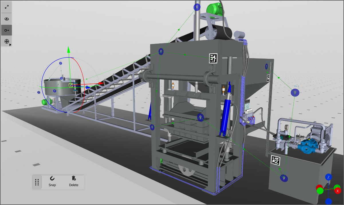
All markers can be downloaded by clicking on Marker PDF in the top menu. For large models, it is recommended to add more than one marker to facilitate tracking with HoloLens 2. A large model is one that, in order to see all pins, the user needs to move their point of vision more than 90 degrees in relation to the position of the original marker. If this is the case, add an additional marker to each section (i.e., side) of your real-life component. Each marker helps the device recalibrate the position of the pins, assuring their correct placement.
Object Trackers
When using object trackers, the real-life object is used to calculate the position of the information that is to be displayed within a workflow at the desired spot. Object trackers can be used in workflows that will be viewed on HoloLens 2, iOS, and Android devices.
To add an object tracker to your model:
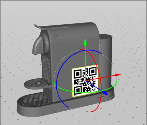
- Click on Add > Object Tracker in the menu at the top of the 3D scene.
- You will see a red hologram of smart glasses (you need to zoom out using the scroll wheel on your mouse). This hologram shows how the object will be perceived through smart glasses.
3. The position of the object tracker in relation to the model in the scene represents the position and distance in which the user will have to position their device to scan the real object while playing the workflow in Spatial Workplace.
4. Add the object tracker. It is now positioned automatically where the 3D scene camera is (i.e., the perspective in which the user is currently looking at the model in the 3D scene).
Note: Using the mouse, the user can rotate the scene to see it better from different perspectives.
5. Use the gizmo over the object tracker to refine its positions or move the camera.
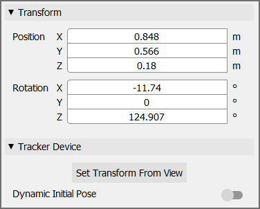
6. Optional: Click on Set Transform From View in the menu on the right to move it again to your viewing perspective.
Note: It is important that the object tracker is at a reasonable distance from the model and that the line coming out of it is pointing to the model.
⇒ After uploading your workflow, test the scanning perspective and distance on a viewing device and fine-tune it in the editor. With this, it will be guaranteed for the final user to have a better scanning experience.
Note: The red color of the smart glasses hologram means that there is no .obj file attached. The .obj file aids object tracking from VisionLib to track the real-life component.
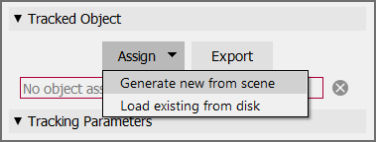
7. To create a .obj file from the scene, select the red hologram
8. Go to settings on the right.
9. Click on Assign > Generate new from scene under Tracked Object
10. Optional: The user can also save the .obj file on their computer by clicking on Export and saving the file.
Note: Independent from the model format imported into Spatial Editor, a .obj file needs to be generated from the scene or provided from disk.
11. Now, the hologram of the Object Tracker in the 3D scene should change its color to green.
12. Optional: If parts are hidden or moved from the model in Spatial, the .obj file needs to be regenerated to include these changes in your workflow. To be able to adjust the position and rotation of the initial tracking when using the Workplace app, enable the Dynamic Initial Pose option.
Note: For object tracking in HoloLens 2, the scale of the .obj is required to be in meters. When generating the .obj from the scene, Spatial will automatically ensure this. However, if the user imports an existing .obj with a VisionLib license from a disk, it is the user's responsibility to ensure that the scale is in meters. Other devices do not have this limitation.
13. Change the position and rotation of the object tracker using the menu on the right.
14. Click on Set Transform From View. The object tracker is automatically moved to the position and point of view of the 3D scene.
15. Finally, you can change the values of the tracking parameters (explained below) to improve tracking for a specific object.
Note: One of these parameters is the Static Scene, which the user can disable if the scene they are working with is dynamic. This feature is currently available on mobile devices only.
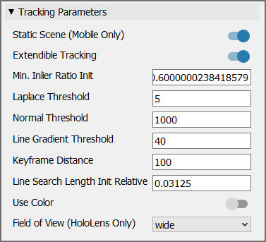
Note: The default values are general parameters chosen to work well with most objects.
Here's a list of all available tracking parameters:
- Dynamic Initial Pose: When enabled, the user can dynamically set the initial tracking viewpoint during runtime.
- Continuous Tracking (Mobile Only): If enabled (default) the object tracker would have continuous object tracking for mobile devices. It is more suitable for objects that can be moved or rotated during the task but keep their form. Non-continuous tracking only tracks the object at the start of the task and then continues the tracking using SLAM. Non-continuous tracking is more suitable for objects that are not moved or rotated during the task and that change their form (e.g. parts are added or removed).
- Extendible Tracking: If enabled (default), the model-based tracking will be extended with SLAM-based tracking. This allows tracking to be continued even if the model isn't visible in the camera image anymore. The user needs to perform a SLAM dance, which means translating and rotating the camera so that there is enough baseline for the feature reconstruction.
- Min. Inlier Ratio Init: Threshold for validating tracking during initialization. The value range reaches from 0.5 to 0.9, with 0.6 being the default value. Higher values are recommended if the line model matches the real-life object perfectly with no occlusion. However, usually they will not match perfectly, which is why a lower value works better.
- Laplace Threshold: Threshold for creating the line model (mm). The value range reaches from 0.0001 to 100000, with 5 being the default value. This specifies the minimum depth between two neighbouring pixels to be recognized as an edge.
- Normal Threshold: Threshold for generating the line model. The value range reaches from 0.0001 to 1000, with 1000 being the default value. This specifies the minimum normal difference between two neighbouring pixels necessary to be recognized as an edge. Usually, it is set to a high value because normal-based lines can't be recognized very reliably. Though, for certain models, it might make sense to use a lower value.
- Line Gradient Threshold: Threshold for edge candidates in the image. The value range reaches from 0 to 256, with 40 being the default value. High values will only consider pixels with high contrast as candidates while low values will also consider other pixels. This is a trade-off. If there are too many candidates, the algorithm might choose the wrong pixels. If there are not enough candidates, the line model might not stick to the object in the image.
- Keyframe Distance: Minimum distance between keyframes (mm). The value range reaches from 0.001 to 100000, with 100 being the default value. The line model is only generated for certain keyframes. Higher values improve performance but come with lower precision (and vice versa).
- Line Search Length Init Relative: Length of the orthogonal search lines (in per cent) relative to the minimum resolution during initialization and tracking. The value range reaches from 0.00625 to 1, with 0.03125 being the default value. The model-based tracker projects the 3D line model into the camera image and searches for edge pixels orthogonal to the projected lines.
- Use Color: This is disabled by default. If enabled, colored edges are distinguished better while tracking. It is only useful for objects with colored edges. It can increase the tracking quality but requires more processing power.
- Field of View (HoloLens 2 Only): A larger field of view makes the object appear smaller during image capturing. It is recommended to use 'wide' for large objects and 'narrow' for small ones.
Note: Object Tracking has to be enabled by TeamViewer/VISCOPIC. Extra licensing per model or per device is required (external software supplier - VisionLib)
Model Placement
Model placement uses the user position when Spatial Workplace was started to position all models and pins connected to the spatial reference.
It can be used in workflows that will be viewed on HoloLens 2, iOS, and Android devices.
To add a model placement spatial reference:
- Click on Add > Model Placement on the top of the 3D scene. The gizmos allow movements only along the green and red axes and rotation around the blue axis. This restriction is meant to keep the model placement reference on the same plane.
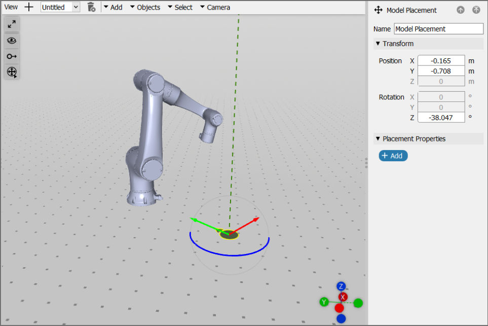
2. The green arrow symbolizes the view direction of the user. The user can choose which models are positioned according to this reference in the menu on the right. When starting the workflow in Spatial Workplace, the selected models and connected pins will be positioned in relation to the viewing direction of the user when they start the Spatial Workplace app.
Model visibility: Different from the pins connected to a spatial reference, models will not be visible by default. To make them visible while playing the workflow, you need to either:
Tracking Recommendations
Marker sizes
The size of the marker can influence the precision with which information is displayed in Spatial Workplace and also the distance from which the marker can be scanned. The editor allows the user to choose a marker size between 1 and 99 cm.
On a HoloLens device, a Frontline marker can be comfortably scanned from a distance 50 times bigger than the marker's size. For example, a 10 cm marker can be scanned until approximately 5 meters away in good lighting conditions. Consider increasing the marker size in case of low-light settings. On iOS and Android devices, Frontline a marker can be comfortably scanned from a distance 5 times bigger than the marker's size (e.g., a marker with a size of 10 cm from a distance of 50 cm).
Note: In general, the minimum recommended size for a marker is 10 cm. However, this might vary according to lighting conditions, camera focus, and the distance from the scanner camera.
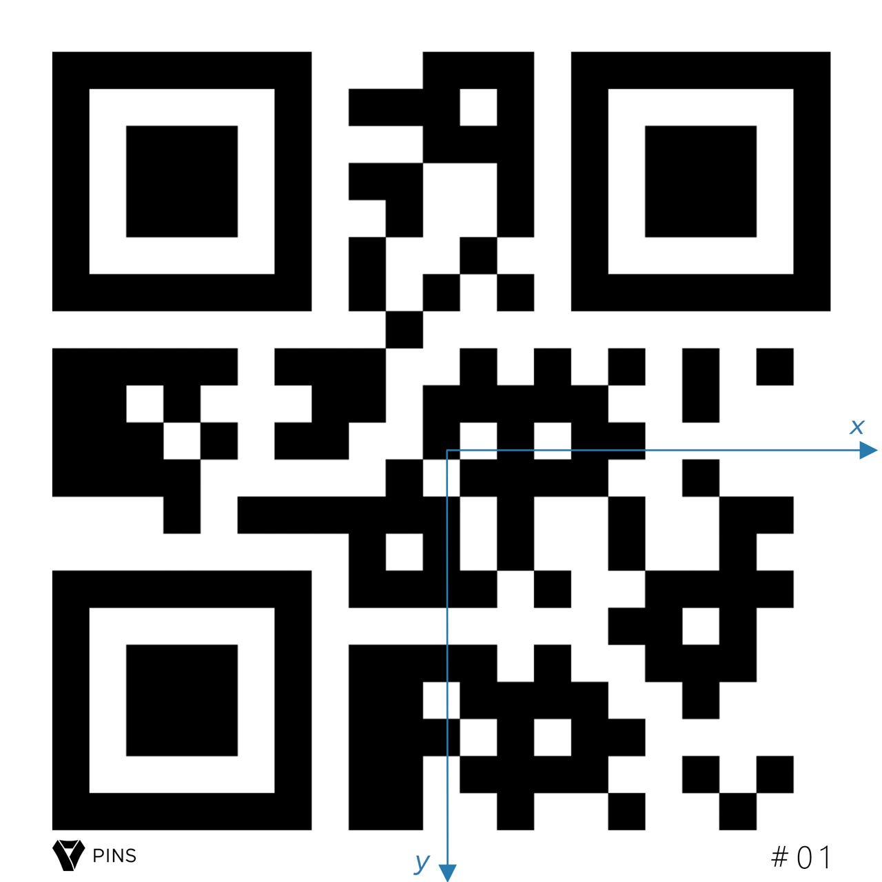
Spatial Workplace positions the content of a workflow in relation to the scanned marker.
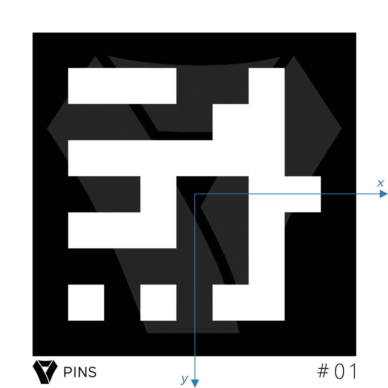
Only the x- and y-axes are shown in this 2D representation. Spatial Workplace, however, also uses the third axis to map the exact 3D position. The software uses the center of the marker in relation to its height and width to determine a 3D transformation.
By placing a marker on the real-life component that has a different size than the digital one added to the workflow in the editor, the user faces the possibility of setting the starting point of this spatial coordinate system in the wrong location. This can compromise the positioning of all the information in the workflow.
Rule of thumb: A size of 10 cm for ArUco markers and 15 cm for QR code markers is enough for most cases on the respective devices. However, lighting conditions, camera focus, and the distance from the scanner camera may have a significant impact. Consider increasing the size of your markers in case of problems.
Note: All four corners of the marker must be clearly visible for the scanner camera and be flattened to the exact position as defined in the editor. Curls and wrinkles in the marker might compromise the correct positioning of pins.
Real-life setting recommendations
Taking care of all tracking variables is important for positioning the pins at their exact spot and minimizing offset. This includes the physical characteristics of the marker, the environment, and the device used for running the Spatial Workplace application. To achieve the best possible results, follow the below-listed recommendations to increase tracking efficiency.
Marker conditions:
- Use a marker with the correct size and ID number as defined in the editor.
- All four corners should be clearly visible for the scanner camera, including the white space around it.
- The marker should always be flattened and placed in the exact position on the real-life object without curls, rips, or wrinkles.
- Reflective surfaces covering the marker can compromise the tracking (e.g., glass or lamination).
- Markers should always be scanned from an angle of 90 degrees in relation to the surface on which they are placed (i.e., the camera should be looking directly at the object/marker). Scanning from different perspectives can influence the positioning of pins.
Environmental conditions:
- The number of features in the environment and your component influence tracking. After the marker is scanned and the original position is set, the device tracking system takes control of keeping the content in its place. The number of features in your setting increases the efficiency of device tracking. Good features include corners and contrast visible on the component itself and between the component and its environment.
- The room should have good lighting. The devices' cameras usually have lower capacities for receiving light in relation to our eyes. Make sure that there is enough light in the room to ensure the best possible tracking results. However, also avoid environments that are too bright.
- Reflective surfaces should be avoided, especially for placing markers, pins, and other content.
- Brusque movements during a task run can cause drifts in the position of the content. Keep a stable position of the device during task performance.
- In large settings, the further away a pin is from the position of the scanned marker, the bigger the chance of undesired drifts in content positioning. This is caused by the intensification of small inaccuracies in marker tracking and by the amount of necessary movement between the marker and the content location. To minimize this problem, check the "Adding extra markers to improve tracking" section below.
Note: Depending on the size of your component, extra markers may be necessary. Due to the limited tracking capabilities of some devices, adding multiple markers for different sections of the model may become necessary. This way, the Spatial Workplace software can re-track the position of the pins to correctly place them. The reposition task function can be used at any time when performing a task to re-track.
Device conditions:
- HoloLens devices
- HoloLens devices require a clean visor and sensors that are free of obstructing objects.
- Looking around the room or walking around the area increases the device's ability to track the room's setting. Having many people that are constantly in motion in the room can compromise tracking.
- Users have different interpupillary distance (IPD). Uncalibrated IPD values on the device can compromise the AR experience. This Microsoft article explains how to use a calibration app to customize the IPD of your device.
- iOS and Android devices
- Clear camera lenses are necessary for correct tracking.
- Auto-focus can compromise the positioning of pins.
Restarting tracking during a task
If there is a drift in the position of your content in the middle of a task run, simply re-scan a marker. Select Reposition Task in the task menu of the device and scan the marker as prompted. After re-scanning the marker, the task will resume starting right where you left off.
Task menu
On mobile devices (iOS and Android), the task menu always stays in the top left corner of the screen with an icon that has three lines in it. On HoloLens 2, the task menu is shown when raising your left hand in front of the device. It is also possible to restart tracking using the "Reposition Task" voice command.
Adding extra markers to improve tracking
AR devices have better tracking capability when all pins are located closer to the spatial reference (marker) and do not require the user to move far away or do big turns in relation to the original position. When content is distant from the initial spatial reference, small tracking inaccuracies from the marker scan will appear bigger, because they are potentialized by the distance. In addition to this, excessive user movement might cause extra drifts in the position of the content.
This is the reason why we recommend creating different markers for different "sections" of the real component, as shown in this example:
During a task run, the user is able to scan new markers in each section of the component and the device can reload the positions of the content and place the pins at their correct positions. For more details, check the "Restarting tracking during a task" section above.
When adding more than one marker to a project in the editor, make sure that the extra markers are connected to the pins in the workflow. In the editor, the user can connect them in the 2D Connector. This allows the user to decide if different markers can start the task from different pins or if the markers will be added in between pins, which will oblige the user to scan that marker when they reach this part of the task. Feel free to use different marker IDs or the same marker ID for these additional markers.
Additional Recommendations
Please take into account the following elements to ensure a seamless AR tracking experience, enhance tracking quality, and prevent problems like AR swimming and incorrect positioning:
- Very few optical features in the real-world environment: If the real-world environment doesn't contain a lot of optical features (e.g. a plain white wall with texture), it can be hard for the cameras to compute the headset or mobile device movements.
- Very complex 3D models/holograms: High computation power is needed when visualizing complex models or holograms in order for all objects/ parts to be visible, meaning that less computing power is left for the AR tracking system.
- No eye calibration (for HoloLens users): The best HoloLens experience can be achieved when each user performs on-device eye calibration. If the issue of "swimming" persists on HoloLens 2, try running eye calibration on your device. Learn more about HoloLens calibration on Microsoft's documentation page.
- Mobile device with limited computing power: If the device you are using to run Spatial Workplace doesn't have strong computational power, it can be that the AR Tracking experience is not smooth.
- Low-quality camera of mobile device: Bad tracking quality can also occur if the quality of the camera of your device is low.
- Wrong marker sizes: Markers have to be printed exactly at the size stated in the marker PDF. Wrong marker sizes result in wrong position tracking since the camera perceives that the marker is e.g. further away if the marker is printed smaller.
- Room scanning might be helpful: If the workflow is used in the same room only, it might help to scan and teach the room to the HoloLens. This can be done by tapping in the air in all directions of the room when using the HoloLens in idle mode (turned on, but no app running).
- Walking large distances/Turning a lot: It is possible that the holograms and pins are misplaced when the user is walking large distances with the device while the Frontline Spatial app running or if the workflow requires many 90-degree turns of the user. A way to remedy this could be to add markers in the middle of the workflow to reset the AR Tracking/the pins' positions.
- Wrong placement of marker in the real world: It is important that the marker is exactly placed/glued at the same position in the real world as it was defined in the virtual scene within the Spatial Editor. This helps with the correct placement of objects and tracking, so ensure that the real-world position of the marker matches the one inside the Spatial Editor.
- Low-powered mobile device: If the device you are using to run Spatial Workplace doesn't have strong computational power, it can be that the AR Tracking experience is not smooth.