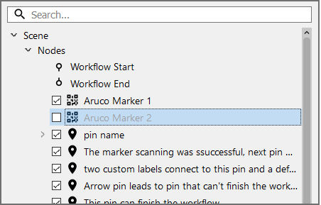
The Scene Explorer is located on the left side of the scene. It shows the nodes and models of the scene.
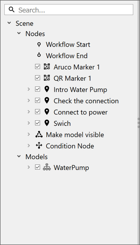
- Search bar: Allows users to search for nodes and models
- Scene: Comprises all of the nodes and models in a project
- Nodes: Refers to workflow elements that can be added by the user
- Models: Refers to 3D models imported to the project
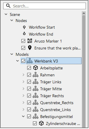
Depending on how the imported model was created, the list might be organized in assemblies. This is particularly useful for selecting whole groups of parts at once. In the above example, all subordinate parts of the "Befestigungsmittel" assembly easily can be selected at once by clicking on the assembly name. This comes in handy when adding holograms to pins or hiding parts of a model.
Note: The Scene Explorer can be resized by dragging the right edge of the list.
Node settings
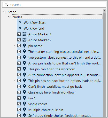
You can select all the user-created items of a scene by clicking on Nodes (displayed right under Scene).
By separately clicking on each node, the respective settings panel for the respective node appears on the right of the scene. These settings are the same as the ones available when the node is added to the scene, be it a pin, marker, scene state, or condition node.
Model settings
You can change the disposition of the whole 3D model, its coordinates, and metrics using the model settings.
To open the settings for a model, select its root element (displayed right under Scene > Models). The root element is the topmost item and contains all of the model's other assemblies and parts.
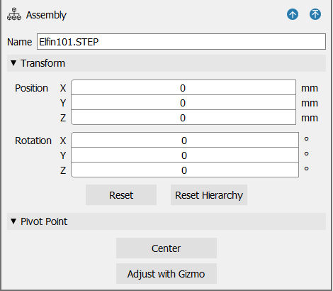
The Product Settings menu opens on the right side of the Editor:
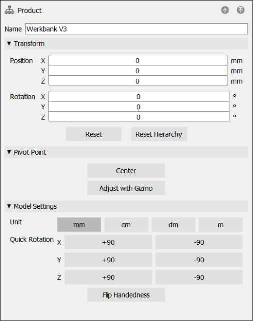
The main functionalities of these settings are:
- Transform: Allows you to edit the position and rotation of the whole model along its axis. The reset buttons below restore the original position and rotation.
- Pivot point: Allows you to adjust the pivot point of an assembly. The pivot point is the point of a part/assembly/model, around which the model rotates. Move this point directly to the center of a part or the model by clicking on Move to Center. Alternatively, click on Adjust with Gizmo to use the item's gizmo to move the point where you want it to be.
Note: The pivot point can be moved for individual parts, assemblies, or the whole model.
- Quick-rotate: Allows you to rotate the model on the respective axis by using the respective buttons. The toggle below may be selected to rotate all items (e.g., pins and markers) to rotate along with the model.
- Model scale: Allows you to change the scaling unit that directly affects the size of all pins, media, and icons in relation to the model. The software will adapt its scale automatically to most 3D models, however, for some exceptions (e.g. .fbx models), the user will have to select it manually using this function. For reference, a pin has a diameter of 10 cm.
- Coordinate system: Allows you to choose between a right-handed or a left-handed coordinate system. When using a right-handed coordinate system, the positive x-axis points right, the positive y-axis points up, and the negative z-axis points forward. When using a left-handed coordinate system, the positive x-axis points right, the positive y-axis points up, and the positive z-axis points forward.
Note: To correct a wrongly displayed model, you can use a combination of quick rotations and coordinate systems changes.
You can also delete a 3D model from the Scene. Apply the following steps to do that:
- Open the Model Explorer from the left side of the Scene
- Select the root node of the model that you want to delete
- select Delete Model from the menu on the right
Assembly/Part Settings
The Assembly or Part Settings menu appears on the right when selecting any part or assembly that is not the root element.
The main functionalities of these settings are:
- Transform: Allows you to modify the position and rotation of the assembly or part as well as to reset the respective defaults.
- Quick-navigate buttons: Allow you to move the currently selected item to the parent assembly or to the top assembly (root element).
Hiding parts
You can hide user-created nodes or model parts/assemblies. To do this using the Scene Explorer, tick or untick the box next to the desired element to hide or show it respectively.
This is available for all parts and nodes, except for the default Workflow Start and Workflow End nodes as well as the Scene State and Condition Nodes.
Alternatively, you can click on the element in the scene to select it, then use the Objects > Hide/Show option from the top menu or the Ctrl + H keyboard shortcut.
Selecting multiple parts
Multiple parts can also be selected in the Scene Explorer and the 3D scene by holding down Ctrl while selecting. The keyboard shortcut H can be used to hide all the selected parts at once.